Welcome Guest,Register Now
Log In

ANT Forum

Welcome guest, please Login or Register


Cant comunicate Arduino => AP2

Rank

Total Posts: 13

Joined 0

PM

// test för att se om chippet fungerar, skickar bara ett meddelande och ser om vi får svar

#include <SoftwareSerial.h>

#define UCHAR unsigned char
#define MESG_TX_SYNC ((UCHAR)0xA4)
#define MESG_SYSTEM_RESET_ID ((UCHAR)0x4A)
#define MESG_CHANNEL_ID_ID ((UCHAR)0x51)

// set up serial communication pins (RX/TX)
SoftwareSerial Serial1(0, 1);

// setup serial communcation and send reset and SetChID message
void setup()
{
Serial1.begin(4800);
Serial.begin(115200);
delay(5000);
Serial1.flush();
reset();
delay(1000);
SetChID();
delay(1000);
}

// listen for message
void loop(){
int sbuflength = Serial1.available();
while(sbuflength > 0) {
Serial.print("got message: ") ;
}
}

// reset message
void reset (){
uint8_t buf[5];
buf[0] = MESG_TX_SYNC; // SYNC Byte
buf[1] = 0x01; // LENGTH Byte
buf[2] = MESG_SYSTEM_RESET_ID; // ID Byte
buf[3] = 0x00;
buf[4] = checkSum(buf,4) ;
ANTsend(buf,5) ;
}

// set channel id
void SetChID()
{
uint8_t buf[9];
buf[0] = MESG_TX_SYNC; // SYNC Byte
buf[1] = 0x05; // LENGTH Byte
buf[2] = MESG_CHANNEL_ID_ID; // Assign Channel ID 0x51
buf[3] = 0x00; // channel number
buf[4] = 0x05; // Device number
buf[5] = 0x00; // Device number
buf[6] = 0x0B; //Device type ID
buf[7] = 0x00; //Transmission type
buf[8] = checkSum(buf, 8) ;
ANTsend(buf,9);
}

// send message to chip
void ANTsend(uint8_t buf[], int length){

Serial.print("Sent TX: ") ;

for(int i = 0 ; i <= length ; i++){
Serial.print(buf, HEX);
Serial.print(" ");
Serial1.write(buf) ;
}
Serial.println("");
}

// create checksum for message
UCHAR checkSum(UCHAR *data, int length){
int i;
UCHAR chksum = data[0];
for (i = 1; i < length; i++){
chksum ^= data;
}
return chksum;
}      
Avatar
RankRankRankRank

Total Posts: 745

Joined 2012-09-14

PM

Hi,

I need more information such as timing diagrams, which pins are connected where, which Arduino your using etc.

I can make a few comments though.

I strongly recommend using the RTS/CTS line. It lets you know when ANT is ready to receive new messages. There is no fixed timing for how long it may take ANT to finish receiving a new serial message.

If your not using a 3.3V Arduino then you need to have level shifters in between the AP2 and the Arduino.

I just posted this in another thread but here's an example of what a MCU to AP2 message (reset system command) would look like.

[img size=796]http://www.thisisant.com/images/fbfiles/images/Reset_Message-71ea286c629d25a5b835de9cfc2f8006.png[/img]

Cheers      
Rank

Total Posts: 13

Joined 0

PM

Hi!

There must have been some problems with my post since only the code was posted.

The wireing (AP2 -> Arduino UNO):
1 - GND
2 -
3 - VCC
4 - GND
5 -
6 - GND
7 - VCC
8 -
9 - GND
10 - GND
11 - RX
12 - TX (with two resistors as current-divider)
13 - GND
14 - GND
15 - GND
16 - GND
17 -

This should give me 4800 async.

The strange thing is if I messure on RX on the arduino-card it is 5v, that doesnt feels good.

If I have sent 5v to the chip are there any idea to troubleshoot it or shall I order a new one?

How shall I connect RST and how to integrate it in my program?

Thanks!      
Avatar
RankRankRankRank

Total Posts: 745

Joined 2012-09-14

PM

Hi,

Even if your powering the module from the 3.3V line, a regular Arduino is still a 5V device, so it's IO lines are being driven by the 5V rail.

Your AP2 may still be alive assuming the Arduino hasn't driven any current into the AP2 through the IO lines but I can't guarantee anything. There are some issues in your pin configuration.

Your pin 6 should be pulled up to VCC. If your not planning to use the suspend signal it's active low.

I would recommend using sleep to save power but if that's not a concern then keep sleep (pin 7) tied to GND. It's mentioned in the "Interfacing with ANT General Purpose Chipsets and Modules" document.

Also I'm not sure why your using a resistor divider anywhere, if that's for level shifting then unfortunately that doesn't work. If you go down a custom level shifter route you need to use transistors, but I'd strongly recommend just buying a part to do it for you. Also the level shifting would have to applied to every I/O line between the module and the Arduino board.

For the RTS line, just wait to make sure it's low before you send any ANT commands. You should still wait for the response message, but you should also check if RTS is low first before sending a new message.

Cheers      
Rank

Total Posts: 13

Joined 0

PM

Thanks for your answer, since I had +5v on the RX on the arduino I have put +5v on the ant TX port so I guess it is gone.

Ok, so I:
- Change to a levelshifter on both RX/TX
- #6 to VCC
- #7 to GND (I have power avaliable all the time)
- Vire the RTS to a digital-pin and check that it is low before sending a message

Thanks a lot! I can post a update when I get the levelshifter and the new chip (2weeks delivery-time, again). smile      
Avatar
RankRankRankRank

Total Posts: 745

Joined 2012-09-14

PM

Glad to help smile

As a note you can also buy 3.3V Arduino boards, I think I have one bumping around myself...

Also I'd feel safer if that RTS line was at least buffered , if not level shifted properly to prevent any reverse current events from occurring. It should be ok though...

Cheers      
Rank

Total Posts: 13

Joined 0

PM

Good point about the RTS! I have orderd this levelshifter: https://www.sparkfun.com/products/8745

So I guess I can run RX/TX in one channel and RTS on the other.

Is RTS a "must have" or will work without? I actaully only wants to send messages with the board so there is really no need for reading (except to make sure the communication works).      
Avatar
RankRankRankRank

Total Posts: 745

Joined 2012-09-14

PM

The RX and TX lines are asynchronous of each other, which means they can be active simultaneously, you must have separate channels for each of them.

RTS lets you know when your allowed to send any command to the chip. I realize it's a bit of a pain but it prevents any commands sent to ANT at poor times from either being dropped, causing an unintended state transition, etc.

If you really want to avoid level shifting an RTS, I can think of a few options.
1) Plug it into an analog in, those should be well buffered but I can't guarantee the latency (how long it takes to poll). This is probably your best free option.

2) Since you just need to read it, buffer it through an op-amp if you have one on hand. Otherwise level shifters are probably still cheaper (only a couple FETs).

3) I STRONGLY DISCOURAGE going this route...but you can try to put a fixed wait time between sending messages to the network processor. It would make bursting virtually impossible but if it's just a hobby project, putting about 2 ms between each message to the AP2 should probably keep you clear.

Cheers      
Rank

Total Posts: 13

Joined 0

PM

As far as I understand the https://www.sparkfun.com/products/8745 can handle RX/TX on "one" channel, two cables.

I think option 1 sounds good and since Im just making a simple hobby-project I might go with option 3 during the testing.

Thanks a lot! smile      
Rank

Total Posts: 13

Joined 0

PM

Hello again!

I got the new chip now and tried it but didnt get it to work, so I need some help in trouble-shooting.

The parts I use are:
Arduino UNO+5v
Sparkfun Levelconverter (LC): https://www.sparkfun.com/products/8745?
Ap2-chip

Im doing the RX/TX switching between the UNO and the LC.

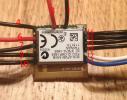
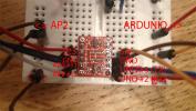
Im using the SW with the code above with a change, RX=#2 and TX=#3, and you can see the viring im using in the attached images.

Can you see what Im doing wrong?
The way I expect the code to work is to send a message over TX/RX the to chip and expect a answer in return, this is the right way how it should work, right?

In the vire-picture, red = 3.3, black = GND.

On the LC on the RX-line the level-converting are done by resistors, does this mean I have to use both TX lines (ch1 AND ch2) in the LC instead?

Is it correct to make the TX/RX switch between the UNO and LC or shall I do this between the LC and the AP2 Instead?

Going:
UNO TX-> LC TXO => LC TXI => AP2 RX
AP2 TX -> LC RXO => LC RXI => UNO TX

If a meassure on the TX / RX lines on the AP2 they have 1,8V resp 2.4V while "idle" can this be correct?

Thanks in advance and have a great weekend! smile
     

Image Attachments

ap2.jpgap22.jpg

Click thumbnail to see full-size image

Avatar
RankRankRankRank

Total Posts: 745

Joined 2012-09-14

PM

I'd be a little wary of that RX line design on the level converter, without at least a buffer you can't guarantee the quality of the voltage coupling. At the very least that resistor divider should be 10K and 20K, not 10K/10K.

First I would try:
The resistor divider should be used going from Arduino TX -> AP2 RX with 10K/20K.
The transistor should be used going from AP2 TX -> Arduino RX.

After I would try both on the transistor shifters, just make sure to keep the Arduino on the HV side and AP2 on the LV side, it works bi-directionally.      
Rank

Total Posts: 13

Joined 0

PM

Harrison - 16 November 2012 06:04 PM
I'd be a little wary of that RX line design on the level converter, without at least a buffer you can't guarantee the quality of the voltage coupling. At the very least that resistor divider should be 10K and 20K, not 10K/10K.

The resistor divider should be used going from Arduino TX -> AP2 RX.
The transistor should be used going from AP2 TX -> Arduino RX.

The transistor level shifter works best going from Low Voltage TX to High Voltage RX. It can kind of work in reverse but the the Drain–Source Diode Forward Voltage won't allow the low voltage side to drop to 0 (datasheet says 0.8V to 1.4V).


Thanks for reply, but isnt this how it is connected at the moment?
Arduino TX => RXI (LC) => RXO (LC) => AP2 RX
and:
AP2 TX => TXI (LC) => TXO (LC) => Arduino RX

According to: http://www.sparkfun.com/datasheets/BreakoutBoards/Level-Converter-v10.pdf it looks like there is a resistance-devider on the RX-line.

Or do I miss something? smile      
Avatar
RankRankRankRank

Total Posts: 745

Joined 2012-09-14

PM

I'd try Arduino TX to TXO and AP2 RX to TXI
Arduino RX to TXO and AP2 TX to TXI

I was a bit mistaken, the transistor's forward diode voltage is small enough all the time to ensure it turns on so it should work bi-directionally here.      
Rank

Total Posts: 13

Joined 0

PM

Harrison - 16 November 2012 06:21 PM
I'd try Arduino TX to TXO and AP2 RX to TXI
Arduino RX to TXO and AP2 TX to TXI

I was a bit mistaken, the transistor's forward diode voltage is small enough all the time to ensure it turns on so it should work bi-directionally here.


Ok! I will do that tomorrow and post a update!

Another question, will the software work as I expect; sending a message to the chip and wait for the answer? This is the right approach, right?      
Avatar
RankRankRankRank

Total Posts: 745

Joined 2012-09-14

PM

It should work as long as the UART baud rate settings match, send the reset message first (while RTS is low). I'll repost the example from a logic analyzer.


Image Attachments

temp_file_Reset_Message1.png

Click thumbnail to see full-size image

Rank

Total Posts: 13

Joined 0

PM

Harrison - 16 November 2012 06:21 PM
I'd try Arduino TX to TXO and AP2 RX to TXI
Arduino RX to TXO and AP2 TX to TXI

I was a bit mistaken, the transistor's forward diode voltage is small enough all the time to ensure it turns on so it should work bi-directionally here.


Hello!

I tried vire as you suggested buy there was no differance, no answer from the ap2. Are there any way to test that it is working?

Im not check the RTS but wait 1000ms between messages:
reset();
delay(1000);
SetChID();
delay(1000);

this should be ok, right?

Im thinking about change to another microcontroller maybe I have better luck with a 3.3V.

I think about the Arduino Pro Mini. Do you have anyone you recommend to which I can find a vireing-diagram and some code to work from?