Welcome Guest,Register Now
Log In

ANT Forum

Welcome guest, please Login or Register


MSP430G2553 USI - Async port interface with ANT AT3 module

Rank

Total Posts: 5

Joined 2013-04-29

PM

Hello!

Currently I'm trying to interface an ANT AT3 module with a Launchpad with an MSP430G2553 on it.
I've wired the module as described in 'D00000794_Interfacing_with_ANT_General_Purpose_Chipsets_and_Modules_Rev_2.1' paper.
And written a program where I can sent first of all a reset command. Additionally I've attached a logic analyzer at the RTS signal port. My expectation was that when I sent the reset command the RTS signal mus go high.
But the RTS signal line stays low. Next I've written a program to pair with an SUUNTO movestick mini who's working together with the AntWare II application. I've configured the movestick as an slave device and waiting for incoming messages. Sometimes the movestick receives messages from the AT3 module but not predictable.

In all the time the RTS signal stays low. What can be the problem?


greets

-René      
RankRankRankRank

Total Posts: 156

Joined 2013-01-07

PM

Hi René,

Do you have a schematic of your current setup? It would be really helpful if you could provide a diagram of your wiring connection between the MSP430 and the AT3 module.

Thanks      
Rank

Total Posts: 5

Joined 2013-04-29

PM

Hello!

I've taken this picture out from 'D00000975_AT3_RF_Transceiver_Module_Datasheet_Rev_2.3' and modified it a little bit. It's not 100% accurate the pins etc. I've painted in Red as you can see the pins wired on my launchpad to the module.
I'm not using the facility to reset the module via an MCU Port PIN. That's why I marked it with an X. As you can see BR1, BR3 tied to VCC and BR2 tied to GND to configure the module with 9600 baud. I'm not using the SLEEP PIN on the module it's tied to GND so the module always is always ON. VCC and Ground comes from the Launchpad. VCC is about 3.562V.
For know I've written a little program where I configure the module corresponding to the specifications. When I send the data and add little delays between the seperate commands. I was able to pair it with the suunto stick and send data to the module.

But I don't want delay's within the messages I want wo make usage of the RTS signal that says me when the module correctly received commands sended by the MCU.
Additionally I've detected... when I attached my Logic-Analyzer to the the ports RX/TX/RTS the MCU and module behaves a little strange. I can record signals RX/TX but it seems the signal will not be recognized by the module. As soon as I detach the Logic-Analyzer I can again establish a connection.

Btw. I've attached the module to my breadboard with about 10cm long wires at each connection pin. Could it be that this "long" wires are making any problems? Could this lead to any capacitance coupling?

Any suggestions?

Thanks!


regards

-René      

Image Attachments
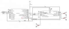
temp_file_Schematic1.png

Click thumbnail to see full-size image

RankRankRankRank

Total Posts: 156

Joined 2013-01-07

PM

Hi René,

Some more questions for you:

What version of Code Composer are you using with the msp430?

Could you send the code you are using to set up the master and transmit messages?

What is your current setup to detect the RTS signal? Is it using interrupts on the MSP430 or the logic analyzer?

Also could you describe your setup with the logic analyzer (possibly a schematic)? The behaviour you have described is probably due to a connection error.

Thanks,

Usama      
Rank

Total Posts: 5

Joined 2013-04-29

PM

Hello!

Sorry for the delay, but at the moment I'm ver busy. :-(
Currently I'm working on this project again!
Still the same problem.
The RTS signal is from the AT3 module is directly connected to the probe of the logic analyzer.
Maybe the current is to low to feed the analyzer. But if I configure a pin on the launchpad as
an IN-PORT and want to trigger a falling or rising edge nothing happends.


greets

-René      
RankRankRankRank

Total Posts: 156

Joined 2013-01-07

PM

LairdTurner - 07 July 2013 05:19 AM

Additionally I've detected... when I attached my Logic-Analyzer to the the ports RX/TX/RTS the MCU and module behaves a little strange. I can record signals RX/TX but it seems the signal will not be recognized by the module. As soon as I detach the Logic-Analyzer I can again establish a connection.

Btw. I've attached the module to my breadboard with about 10cm long wires at each connection pin. Could it be that this "long" wires are making any problems? Could this lead to any capacitance coupling?


It is really interesting that you are able to to open an ANT channel but the RTS signal is not changing at all. I would conclude that the ANT module works fine and double check your connections (considering the behaviour you described earlier with the logic analyser).

It is probably a good idea to minimize the length of the wires, but that is a highly unlikely reason considering all your other signal lines are working fine. If you have another ANT module, try the same set up to see if you get the same result.

If none of those help, could you send me the code (main.c) you are using?


Rank

Total Posts: 5

Joined 2013-04-29

PM

usamak - 24 September 2013 10:56 AM
LairdTurner - 07 July 2013 05:19 AM

Additionally I've detected... when I attached my Logic-Analyzer to the the ports RX/TX/RTS the MCU and module behaves a little strange. I can record signals RX/TX but it seems the signal will not be recognized by the module. As soon as I detach the Logic-Analyzer I can again establish a connection.

Btw. I've attached the module to my breadboard with about 10cm long wires at each connection pin. Could it be that this "long" wires are making any problems? Could this lead to any capacitance coupling?


It is really interesting that you are able to to open an ANT channel but the RTS signal is not changing at all. I would conclude that the ANT module works fine and double check your connections (considering the behaviour you described earlier with the logic analyser).

It is probably a good idea to minimize the length of the wires, but that is a highly unlikely reason considering all your other signal lines are working fine. If you have another ANT module, try the same set up to see if you get the same result.

If none of those help, could you send me the code (main.c) you are using?


Hi!
Currently I've connected a low current LED to an IO Port and set the pin via an interrupt if the mcu detects an
a rising edge on the RTS line. And it worked. Okay I see it blicks. Maybe this has something to do that I've only tried communication in debug mode of CSS. And sometimes it reacts a little strange. Okay... So far so good. Tommorrow I will additionally shortening the connection lines between the mcu and the AT3 board.

The datasheet of the AT3 says that after each correct received command the signal will be deaserted, but in the datasheets it's raised for about 50usek. It's a little confusion for me... Is it normally high and will be deasserted, or is it normally low and will be raised if the command will be received successfully? Programming in general, the datasheet states that I can use a simple state machine for establishing a connection. Have you any idea were I can get such an example code? The examples on the ANT page are really huge. For now I'm not sure how the connection process exactly works. For explanation... I want to establish a connection to a slave node and want to broadcast messages that the slave node receive this messages. Another question... Must I sync my transfer to the AT3 module with the channel rate for example 4Hz, or can I simply send data to the module? The datasheets says I can check I the module returns no error on the RX line. In my test application I'm firiring messages to the ant module. Is this a failure?

Puuh many question. It would be great if you can light in the dark. Attached you'll find my "quick and dirty" code.

Thanks for your help!


greets

-René