Hello!
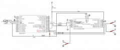
I've taken this picture out from 'D00000975_AT3_RF_Transceiver_Module_Datasheet_Rev_2.3' and modified it a little bit. It's not 100% accurate the pins etc. I've painted in Red as you can see the pins wired on my launchpad to the module.
I'm not using the facility to reset the module via an MCU Port PIN. That's why I marked it with an X. As you can see BR1, BR3 tied to VCC and BR2 tied to GND to configure the module with 9600 baud. I'm not using the SLEEP PIN on the module it's tied to GND so the module always is always ON. VCC and Ground comes from the Launchpad. VCC is about 3.562V.
For know I've written a little program where I configure the module corresponding to the specifications. When I send the data and add little delays between the seperate commands. I was able to pair it with the suunto stick and send data to the module.
But I don't want delay's within the messages I want wo make usage of the RTS signal that says me when the module correctly received commands sended by the MCU.
Additionally I've detected... when I attached my Logic-Analyzer to the the ports RX/TX/RTS the MCU and module behaves a little strange. I can record signals RX/TX but it seems the signal will not be recognized by the module. As soon as I detach the Logic-Analyzer I can again establish a connection.
Btw. I've attached the module to my breadboard with about 10cm long wires at each connection pin. Could it be that this "long" wires are making any problems? Could this lead to any capacitance coupling?
Any suggestions?
Thanks!
regards
-René
Image Attachments

Click thumbnail to see full-size image

