Welcome Guest,Register Now
Log In

ANT Forum

Welcome guest, please Login or Register


ARDUINO + D52QD2M4IA - protocol help…

RankRankRank

Total Posts: 54

Joined 2013-05-15

PM

Hi.
I develop an application in the past with ARDUINO and a nRF24AP2 module with great success. I can read 8 heart rate monitors ANT+ sensors in the same time.
Now I am trying to upgrade my application using a D52QD2M4IA to read 15 or many sensors in the same time.
The main problem I have is a protocol issue.
According to ANT Message Protocol and Usage 5.1 I wrote an ARDUINO library to connect with nRF24AP2. It works. But not with D52QD2M4IA.
I report a protocol dump report between ARDUINO (the Host) and the ANT+ Nordic Modules:

----------------------------------------------- nRF24AP2
started
RX <<< [ A4 1 6F 0 CA ]
1) GETTING CAPABILITIES
TX >>> [ A4 2 4D 0 54 BF ] len=6
RX <<< [ A4 6 54 8 3 0 B2 36 0 79 ]
Canali massimi disponibili sul modulo :8
100) SET NETWORK KEY - network #: 0 ...
TX >>> [ A4 9 46 0 B9 A5 21 FB BD 72 C3 45 64 ] len=13
RX <<< [ A4 3 40 0 46 0 A1 ]
101) CHANNEL ASSIGN - channel #: 0 - channel type: 64 - network #: 0
TX >>> [ A4 3 42 0 40 0 A5 ] len=7
RX <<< [ A4 3 40 0 42 0 A5 ]
102) SET CHANNEL - channel #: 0 - device number: 0 - device type: 120 - transmission type: 0
TX >>> [ A4 5 51 0 0 0 78 0 88 ] len=9
RX <<< [ A4 3 40 0 51 0 B6 ]
103) SET CHANNEL FREQUENCY - channel #: 0 - frequency: 57
TX >>> [ A4 2 45 0 39 DA ] len=6
RX <<< [ A4 3 40 0 45 0 A2 ]
104) SET RX EXT MESSAGE ENABLE - enable: 1
TX >>> [ A4 2 66 0 1 C1 ] len=6
RX <<< [ A4 3 40 0 66 0 81 ]
105) OPEN SCAN MODE (CONTINUOUS)
TX >>> [ A4 1 5B 0 FE ] len=5
RX <<< [ A4 3 40 0 5B 0 BC ]
106) 106) 106) 106) 106) 106) 106


----------------------------------------------- D52QD2M4IA
started
RX <<< [ A4 1 6F 1 CB ]
1) GETTING CAPABILITIES
TX >>> [ A4 2 4D 0 54 BF ] len=6
MESSAGE_READ_INFO_TIMEOUT_MIDMESSAGE
RX <<< [ A4 84 2A 8 4 BA 9B 0 7D 68 FE 0 0 0 0 0 0 0 54 0 1 0 1 0 0 0 1 0 0 0 1 0 0 0 0 0 0 66 8F 0 0 0 0 0 1 9E 5 0 0 E8 3 0 0 0 0 0 0 8 1 23 0 2 25 0 6B 0 1 1 0 1D 0 D 0 1F 0 0 10 10 A4 1 6F 1 CB A4 84 2A 8 4 BA 9B 0 7D 68 FE 0 0 0 0 0 0 0 0 0 0 0 0 0 0 0 0 0 0 0 0 0 0 0 0 0 0 0 0 0 0 0 0 0 0 0 0 0 0 0 0 0 0 ]
Messaggio non atteso!: 2A - Messaggio atteso era: 54
1) GETTING CAPABILITIES
TX >>> [ A4 2 4D 0 54 BF ] len=6
MESSAGE_READ_INFO_TIMEOUT_MIDMESSAGE
RX <<< [ A4 8 4A 8 4 BA 36 0 7D 68 FC 0 ]
Messaggio non atteso!: 4A - Messaggio atteso era: 54
1) GETTING CAPABILITIES
TX >>> [ A4 2 4D 0 54 BF ] len=6
MESSAGE_READ_INFO_TIMEOUT_MIDMESSAGE
RX <<< [ A4 8 4A 8 4 BA 9B 80 FD 43 FC 0 ]
Messaggio non atteso!: 4A - Messaggio atteso era: 54
1) GETTING CAPABILITIES
TX >>> [ A4 2 4D 0 54 BF ] len=6
MESSAGE_READ_INFO_TIMEOUT_MIDMESSAGE
RX <<< [ A4 84 AA 8 4 BA 36 0 7D 68 FE 0 0 0 0 0 0 0 54 0 1 0 1 0 0 0 4 0 0 0 1 0 0 0 0 0 0 66 8F 0 0 0 0 0 1 9E 5 0 0 E8 3 0 0 0 0 0 0 8 1 23 0 2 25 0 6B 0 1 1 0 1D 0 D 0 1F 0 0 31 31 A4 1 6F 1 CB A4 84 2A 8 4 BA 9B 0 7D 68 FE A4 8 4A 8 4 BA 36 0 7D 68 FC A4 8 4A 8 4 BA 9B 80 FD 43 FC A4 84 AA 8 4 BA 36 0 7D 68 FE 0 0 0 0 0 0 0 0 0 ]
Messaggio non atteso!: AA - Messaggio atteso era: 54
1) GETTING CAPABILITIES
TX >>> [ A4 2 4D 0 54 BF ] len=6
MESSAGE_READ_INFO_TIMEOUT_MIDMESSAGE
RX <<< [ A4 84 AA 8 4 BA 9B 80 FD 43 FC 0 0 0 0 0 0 0 54 0 1 0 1 0 0 0 5 0 0 0 1 0 0 0 0 0 0 66 8F 0 0 0 0 0 1 9E 5 0 0 E8 3 0 0 0 0 0 0 8 1 23 0 2 25 0 6B 0 1 1 0 1D 0 D 0 1F 0 0 3C 3C A4 1 6F 1 CB A4 84 2A 8 4 BA 9B 0 7D 68 FE A4 8 4A 8 4 BA 36 0 7D 68 FC A4 8 4A 8 4 BA 9B 80 FD 43 FC A4 84 AA 8 4 BA 36 0 7D 68 FE A4 84 AA 8 4 BA 9B 80 FD ]
Messaggio non atteso!: AA - Messaggio atteso era: 54
1) GETTING CAPABILITIES
TX >>> [ A4 2 4D 0 54 BF ] len=6
MESSAGE_READ_INFO_TIMEOUT_MIDMESSAGE
RX <<< [ A4 84 AA 8 4 BA 3B 0 7D 68 FC 0 0 0 0 0 0 0 54 0 1 0 1 0 0 0 6 0 0 0 1 0 0 0 0 0 0 66 8F 0 0 0 0 0 1 9E 5 0 0 E8 3 0 0 0 0 0 0 8 1 23 0 2 25 0 6B 0 1 1 0 1D 0 D 0 1F 0 0 7 7 4 BA 3B 0 7D 68 FC 2A 8 4 BA 9B 0 7D 68 FE A4 8 4A 8 4 BA 36 0 7D 68 FC A4 8 4A 8 4 BA 9B 80 FD 43 FC A4 84 AA 8 4 BA 36 0 7D 68 FE A4 84 AA 8 4 BA 9B 80 FD ]
Messaggio non atteso!: AA - Messaggio atteso era: 54
1) GETTING CAPABILITIES
TX >>> [ A4 2 4D 0 54 BF ] len=6
MESSAGE_READ_INFO_TIMEOUT_MIDMESSAGE
RX <<< [ A4 84 54 8 4 BA 36 0 F6 1D 8B 0 0 0 0 0 0 0 54 0 1 0 1 0 0 0 7 0 0 0 1 0 0 0 0 0 0 66 8F 0 0 0 0 0 1 9E 5 0 0 E8 3 0 0 0 0 0 0 8 1 23 0 2 25 0 6B 0 1 1 0 1D 0 D 0 1F 0 0 12 12 4 BA 3B 0 7D 68 FC A4 84 54 8 4 BA 36 0 F6 1D 8B 4A 8 4 BA 36 0 7D 68 FC A4 8 4A 8 4 BA 9B 80 FD 43 FC A4 84 AA 8 4 BA 36 0 7D 68 FE A4 84 AA 8 4 BA 9B 80 FD ]
Canali massimi disponibili sul modulo :8
100) SET NETWORK KEY - network #: 0 ...
TX >>> [ A4 9 46 0 B9 A5 21 FB BD 72 C3 45 64 ] len=13
MESSAGE_READ_INFO_TIMEOUT_MIDMESSAGE
RX <<< [ A4 20 0 46 0 D0 36 0 F6 1D 8B 0 0 0 0 0 0 0 40 0 1 0 1 0 0 0 8 0 0 0 1 0 0 0 0 8 ]
Messaggio non atteso!: 0 - Messaggio atteso era: 40
100) SET NETWORK KEY - network #: 0 ...
TX >>> [ A4 9 46 0 B9 A5 21 FB BD 72 C3 45 64 ] len=13
MESSAGE_READ_INFO_TIMEOUT_MIDMESSAGE
RX <<< [ A4 20 0 46 0 A1 36 0 F6 1D 8B 0 0 0 0 0 0 0 40 0 1 0 1 0 0 0 9 0 0 0 1 0 0 0 0 8 ]
Messaggio non atteso!: 0 - Messaggio atteso era: 40
[...]

How I can solve this problem? It seems to using extended message but also if I try to disable them the module seems to ignore it.
Many thanks.      
Avatar
RankRankRankRank

Total Posts: 745

Joined 2012-09-14

PM

Hi,

Could you send which version/markings are on your module? Also if you have a schematic handy that would be great.

My first note is that the startup message you received is slightly suspect:
A4 1 6F 1 CB

This indicates that the watchdog set off the reset, which might mean the Network Processor code crashed. If you use the reset line, does it come back with "0" as the AP2 does?

Thanks      
RankRankRank

Total Posts: 54

Joined 2013-05-15

PM

Hi, and thanks for response...
so
in attach there is a picture of the D52QD2M4IA module.

The wiring I used is:
H202 -> TO ARDUINO PIN FOR RESET FUNCTION
H203 -> VCC
H204 -> GND
H206 -> TO ARDUINO PIN FOR SUSPEND FUNCTION
H207 -> TO ARDUINO PIN FOR SLEEP FUNCTION
H209 -> PORTSEL TO GND (ASYNC)
H210 -> BR2 TO VCC
H211 -> UART TX TO ARDUINO RX
H212 -> UART RX TO ARDUINO TX
H213 -> BR1 TO VCC
H214 -> BR3 TO VCC
H217 -> RTS TO ARDUINO INPUT PIN

BR1-2-3 to VCC = selection of 57600bps serial UART speed


When Arduino starts it execute this routines...

// module reset
void hardwareReset() {
[... some other code ...]
digitalWrite(RESET_PIN, LOW);
delay(5);
[... some other code ...]
hw_reset_count++;
delay(5);
digitalWrite(RESET_PIN, HIGH);
[... some other code ...]
}


// **************************************************************************************************
// * ANT Management Routines
// **************************************************************************************************
void antBegin() {
pinMode(SUSPEND_PIN, OUTPUT);
pinMode(SLEEP_PIN, OUTPUT);
pinMode(RESET_PIN, OUTPUT);
pinMode(RTS_PIN, INPUT);
[... some other code ...]
digitalWrite(RESET_PIN, HIGH);
digitalWrite(SUSPEND_PIN, HIGH);
digitalWrite(SLEEP_PIN, LOW);
//This should not be strictly necessary - the device should always come up by itself....
//But let's make sure we didn't miss the first RTS in a power-up race
hardwareReset();
}


Image Attachments
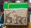
20160926_211655_2.jpg

Click thumbnail to see full-size image

RankRankRank

Total Posts: 54

Joined 2013-05-15

PM

The module sometime give me the following response on capability get command

GETTING CAPABILITIES
TX >>> [ A4 2 4D 0 54 BF ] len=6
RX <<< [ A4 8 56 F 10 0 9D 1B 0 7D 43 F1 ]

but the 0x56 command was not specified on the ANT protocol documentation...
please help me!

     
Avatar
RankRankRankRank

Total Posts: 745

Joined 2012-09-14

PM

Hi,

The AP2 and D52Q are not 100% drop in compatible from a software perspective. The RTS is now hardware controlled on the D52, and bit synchronous operation is no longer supported, as mentioned on page 26 of the datasheet.

Behavior for the nRF52's UART and the RTS line can be found starting from page 332 of the nRF52832 Product Specification. You likely need to make a few tweaks to the driver you are using.      
RankRankRank

Total Posts: 54

Joined 2013-05-15

PM

Hi Harrison,
I've readed the documentation you have suggested me, but I do not understand where is my core issue driving the nRF52832 chip.
What is the correct sequence of signals that I must use to connect correctly and send command from Arduino?
Could you help me?
     
RankRankRank

Total Posts: 54

Joined 2013-05-15

PM

Hi Harrison,

here there is an extraction of my Arduino RTS management code, interrupt and other routines:

// **************************************************************************************************
// *  SETUP
// **************************************************************************************************
void setup() {
[some other code]
  
// We setup an interrupt to detect when the RTS is received from the ANT chip.
  // This is a 50 usec HIGH signal at the end of each valid ANT message received from the host at the chip
  
attachInterrupt(RTS_PIN_INTisr_rts_antRISING);
[some other code]
}

// **************************************************************************************************
// *   ISRs 
// **************************************************************************************************
volatile int rts_ant_received 0//!< ANT RTS interrupt flag see isr_rts_ant()
//! Interrupt service routine to get RTS from ANT messages
void isr_rts_ant() {
  rts_ant_received 
1;
}

// **************************************************************************************************
// *  Loop
// **************************************************************************************************
void loop() {
  
if(rts_ant_received == 1)
  
{
    digitalWrite
(LED_STATUSHIGH);
    
rTSHighAssertion();
    
//Clear the ISR flag
    
rts_ant_received 0;
    
digitalWrite(LED_STATUSLOW);
  
}
}

// **************************************************************************************************
// ! A function that is called when an RTS interrupt is received in the main program
// **************************************************************************************************
void rTSHighAssertion() {
      
//"Waiting for ANT to RTS (let us send again)."
      //Need to make sure it is low again
      
while( digitalRead(RTS_PIN) != LOW {
        
//TODO: Is this a bad idea in an ISR?
        
delayMicroseconds(50);
      
}
      cts 
1// I assume that I can send to nRF a new... next command...
     
Avatar
RankRankRankRank

Total Posts: 745

Joined 2012-09-14

PM

Do you have a logic capture of the UART signals? Could you also list what baud rate you are using? (BR1/BR2/BR3 pin settings)

The RTS can raise while still receiving a message is the major difference between the two.      
RankRankRank

Total Posts: 54

Joined 2013-05-15

PM

as posted in post #2


BR1-2-3 to VCC = selection of 57600bps serial UART speed


Why RTS can change during message receiving?
So how can I manage the RTS signal status?

The reading routine is the following

// ANT reading function
unsigned char antRead() {
  unsigned char byteIn
;
  
unsigned char chksum 0;
  
unsigned long timeoutExit millis() + 5;
  
//First loop will go through always
  
while (timeoutExit >= millis()) {
    
//This is a busy read
    
if (ant_serial.available() > 0{
      byteIn 
ant_serial.read();
      
//We have a byte -- so we want to finish off this message (increase timeout)
      
timeoutExit += ANT_PACKET_READ_NEXT_BYTE_TIMEOUT_MS;
      if ((
byteIn == MESG_TX_SYNC) && (rxBufCnt == 0)) {
        rxBuf[rxBufCnt
++byteIn;
        
chksum byteIn;
      
}
      
else if ((rxBufCnt == 0) && (byteIn != MESG_TX_SYNC)) {
        
return MESSAGE_READ_ERROR_MISSING_SYNC;
      
}
      
else if (rxBufCnt == 1{
        rxBuf[rxBufCnt
++byteIn;       // second byte will be size
        
chksum ^= byteIn;
      
}
      
else if (rxBufCnt rxBuf[1]+3
        
// read rest of data taking into account sync, size, and checksum that are each 1 byte
        
rxBuf[rxBufCnt++byteIn;
        
chksum ^= byteIn;
      
}
      
else {
        rxBuf[rxBufCnt
++byteIn;
        if (
rxBufCnt ANT_MAX_PACKET_LEN{
          
//Likely we are missing something....
          //we reset our buffer count
          
rxBufCnt 0;
          return 
MESSAGE_READ_ERROR_PACKET_SIZE_EXCEEDED;
        
}
        
else {
          rx_packet_count
++;
          if (
chksum != rxBuf[int(rxBuf[1])+3]{
            rxBufCnt 
0;
            return 
MESSAGE_READ_ERROR_BAD_CHECKSUM;
          
}
          
else {
            
//Good packet
            
rxBufCnt 0;
            return 
MESSAGE_READ_INTERNAL;
          
}
        }
      }
    }
  }
  
if(rxBufCnt != 0{
    
//This may be recoverable but it is likely not worth the effort
    //we reset our buffer count
    
rxBufCnt 0;
    return 
MESSAGE_READ_INFO_TIMEOUT_MIDMESSAGE;
  
}
  
return MESSAGE_READ_NONE;


--------------
I tryed to write and read data in total asyncronous mode that is without consider RTS status signal but send a command string like CAPABILITIES REQUEST and check only the response on UART checking returning code. This operates perfectly with nRF24AP2. The main problem is that nRF52832 return a 80 lenght string that seems to be an extended packet with a different returning command. Some of this command was not in ANT protocol documentation. (see 1° post).

1) GETTING CAPABILITIES
TX >>> [ A4 2 4D 0 54 BF ] len=6
MESSAGE_READ_INFO_TIMEOUT_MIDMESSAGE
RX <<< [ A4 84 2A 8 4 BA 9B 0 7D 68 FE 0 0 0 0 0 0 0 54 0 1 0 1 0 0 0 1 0 0 0 1 0 0 0 0 0 0 66 8F 0 0 0 0 0 1 9E 5 0 0 E8 3 0 0 0 0 0 0 8 1 23 0 2 25 0 6B 0 1 1 0 1D 0 D 0 1F 0 0 10 10 A4 1 6F 1 CB A4 84 2A 8 4 BA 9B 0 7D 68 FE 0 0 0 0 0 0 0 0 0 0 0 0 0 0 0 0 0 0 0 0 0 0 0 0 0 0 0 0 0 0 0 0 0 0 0 0 0 0 0 0 0 0 ]
Messaggio non atteso!: 2A - Messaggio atteso era: 54

Thanks      
RankRankRank

Total Posts: 54

Joined 2013-05-15

PM

in this case, for instance, the response is:

1) GETTING CAPABILITIES
TX >>> [ A4 2 4D 0 54 BF ] len=6
MESSAGE_READ_ERROR_BAD_CHECKSUM
MESSAGE_READ_INFO_TIMEOUT_MIDMESSAGE
RX <<< [ A4 8 56 F 18 0 DD 1B 0 7D 43 F1 ]
response message attended!: 56 - Response message given: 54
     
Avatar
RankRankRankRank

Total Posts: 745

Joined 2012-09-14

PM

Hi,

I do not think it is the RTS issue I mentioned earlier as the device hasn't opened a channel yet, and the D52Q has a larger UART buffer which should mitigate the issue, and you have tested the no-UART mode.

Could you please send the logic analyzer view of your TX/RX/RTS/SLEEP/SUSPEND/RESET, etc, lines when you send and receive your first few commands after reset? We need to narrow down if this is garbage being sent by the module or if it's an issue with the framing or the physical connections.

Do you have another D52Q module to do sanity testing against?

Thanks      
RankRankRank

Total Posts: 54

Joined 2013-05-15

PM

Hi Harrison,
I haven't another D52Q module to test. This is the first I bought.
Now I am writing another simplest Arduino code not considering RTS/SLEEP/SUSPEND/RESET but only UART trasmission, so I will send simple command and wait for response. This due to I have not a real analyzer - what do you mean about "analyzer"?
I checked again connection between Arduino and D52Q module mentionend on post #2 and they seem ok.
thanks
     
Avatar
RankRankRankRank

Total Posts: 745

Joined 2012-09-14

PM

Hi,

I will also post later today or tomorrow the Network Processor Source code for the D52Q module so you can reprogram it if you have a JTAG device to do so.

Any logic analyzer or oscilloscope would do. I personally use an old Salae but it looks like their prices have risen slightly.      
RankRankRank

Total Posts: 54

Joined 2013-05-15

PM

Ok and many many thanks for your support.
I have not JTAG, nor oscilloscope.
     
RankRankRank

Total Posts: 54

Joined 2013-05-15

PM

Hi,
there is some other help?
I need support to solve my issues...
please...
     
Avatar
RankRankRankRank

Total Posts: 745

Joined 2012-09-14

PM

Hi,

Sorry, it's a bit difficult without the common embedded debug tools to help. I can try to suggest a few things...

Do you ever assert the SLEEP or SUSPEND lines? You could try never asserting them (keeping them high) if you do use them now.

How long do you wait after receiving the startup message? You could try waiting at least 500ms afterward.

Have you tried an alternate interface such as SPI?

Does the CRC come back correctly during those strings of messages?